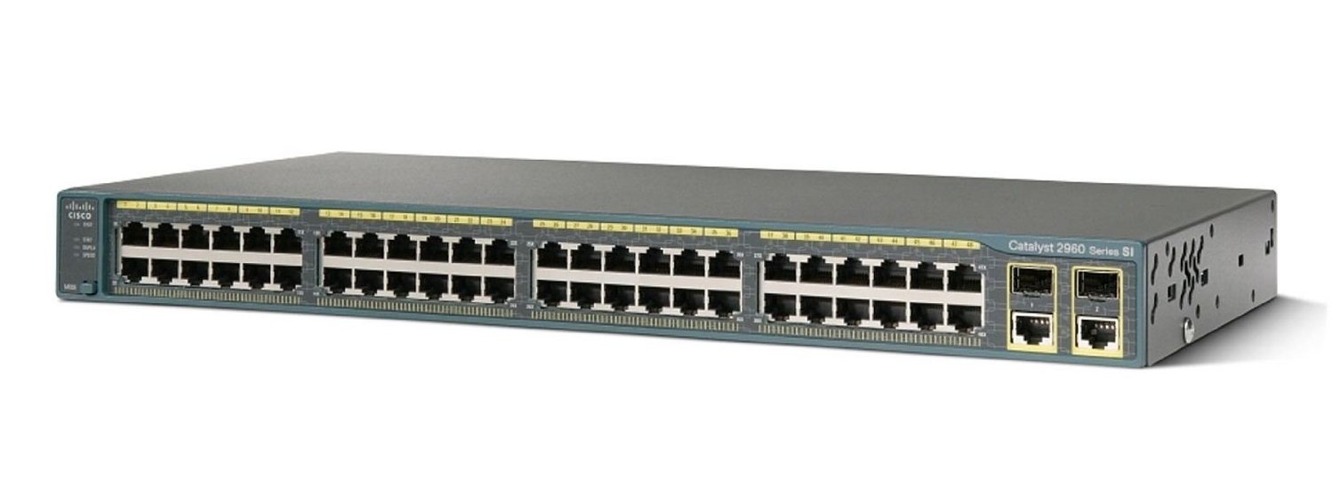
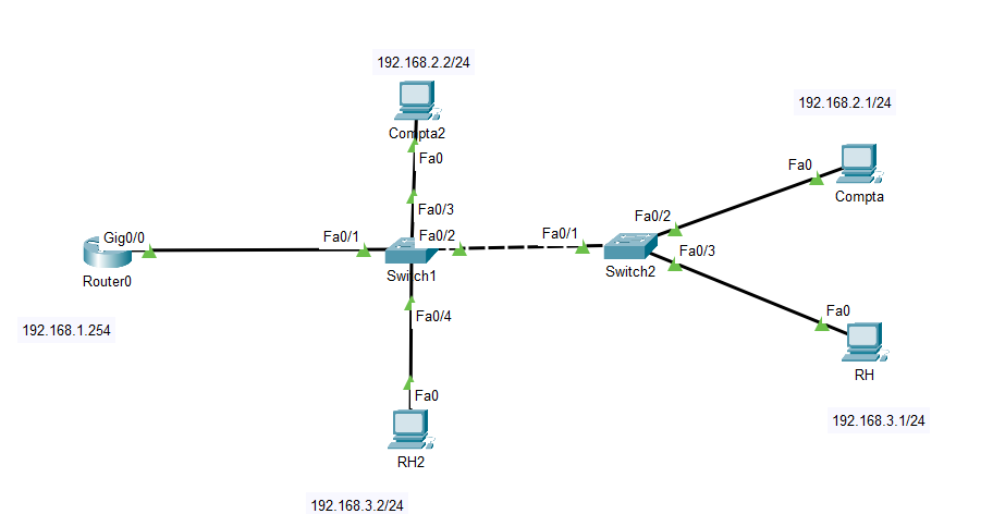
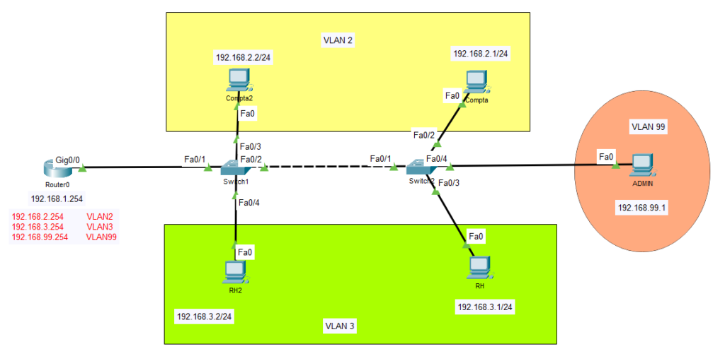
Nous utiliserons Cisco Packet Tracer et un switch Cisco Catalyst 2960.
Rappel des modes de configuration CISCO.
| Router> | User EXEC mode |
| Router# | Privileged EXEC mode |
| Router(config)# | Configuration de mode |
| Router(config-if)# | Interface level within configuration mode |
| Router(config-router)# | Routing engine level within configuration mode |
| Router(config-line)# | Line level (vty, tty, async) within configuration mode |
Un VLAN est une façon de segmenter logiquement un réseau. L’utilisation de VLANs permet d’isoler certaines parties du réseau et donc de les sécuriser. Les VLANs ont aussi d’autres avantages: on peut créer plusieurs réseaux sans mettre de switchs ou de câbles en plus. On peut aussi gérer la QoS en réservant de la bande passante pour un réseau spécifique.
Une trame Ethernet de VLAN a une légère différence par rapport à une trame Ethernet classique: le protocole dot1q. 2 fois 4 octets sont ajoutés (2 pour le VLAN et 2 pour l’Ether Type).

Nous allons créer un premier VLAN sur le switch2.
Switch>en
Switch#conf t
Enter configuration commands, one per line.  End with CNTL/Z.
Switch(config)#vlan 2
Switch(config-vlan)#name compta
Switch#sh vlan brief

VLAN Name                             Status    Ports
---- -------------------------------- --------- -------------------------------
1    default                          active    Fa0/1, Fa0/2, Fa0/3, Fa0/4
                                                Fa0/5, Fa0/6, Fa0/7, Fa0/8
                                                Fa0/9, Fa0/10, Fa0/11, Fa0/12
                                                Fa0/13, Fa0/14, Fa0/15, Fa0/16
                                                Fa0/17, Fa0/18, Fa0/19, Fa0/20
                                                Fa0/21, Fa0/22, Fa0/23, Fa0/24
                                                Gig0/1, Gig0/2
2    compta                           active
1002 fddi-default                     active
1003 token-ring-default               active
1004 fddinet-default                  active
1005 trnet-default                    active
Switch#
Le VLAN2 a été créé. On voit aussi un VLAN1. Il s’agit du VLAN natif. Sur un switch CISCO, par défaut, tous les ports sont configurés sur le VLAN natif.
Nous devons ensuite attribuer un port à ce VLAN. On voit qu’il s’agit de l’interface Fa0/2.
Switch(config)#interface FastEthernet 0/2
Switch(config-if)#switchport access vlan 2
Switch(config-if)#exit
Switch(config)#exit
Switch#
%SYS-5-CONFIG_I: Configured from console by console

Switch#show vlan id 2

VLAN Name                             Status    Ports
---- -------------------------------- --------- -------------------------------
2    compta                           active    Fa0/2

VLAN Type  SAID       MTU   Parent RingNo BridgeNo Stp  BrdgMode Trans1 Trans2
---- ----- ---------- ----- ------ ------ -------- ---- -------- ------ ------
2    enet  100002     1500  -      -      -        -    -        0      0

Switch#
On voit que le port Fa0/2 a été attribué au VLAN2.
A ce stade, nos 2 ordinateurs ne se pingent plus.
On ajoute ensuite un nouveau VLAN pour le service RH.
Switch(config)#vlan 3
Switch(config-vlan)#name RH
Switch(config-vlan)#exit
Switch(config)#interface Fas
Switch(config)#interface FastEthernet 0/3
Switch(config-if)#switchport access vlan 3
Switch(config-if)#end
Switch#
%SYS-5-CONFIG_I: Configured from console by console

Switch#show vlan id 3

VLAN Name                             Status    Ports
---- -------------------------------- --------- -------------------------------
3    RH                               active    Fa0/3

VLAN Type  SAID       MTU   Parent RingNo BridgeNo Stp  BrdgMode Trans1 Trans2
---- ----- ---------- ----- ------ ------ -------- ---- -------- ------ ------
3    enet  100003     1500  -      -      -        -    -        0      0

Switch#
Que faire maintenant si le réseau s’agrandit ?
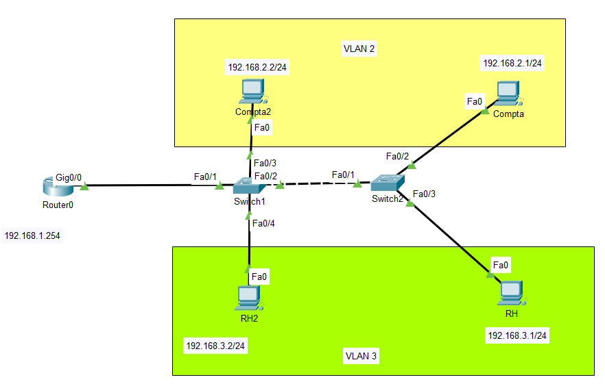
Nous avons le service Compta dans la partie haute du schéma, et le service RH est dans la partie basse. On modifie les adresses IP des machines (numéro du VLAN à la place du 3ème octet).
Sur le switch 1, on configure les 2 VLANs également comme pour le switch2.
Maintenant, nous allons devoir faire passer plusieurs VLANs sur un seul câble: celui situé entre les 2 switchs. Pour ce faire, il faut configurer les interfaces de ce câble en « trunk« . Ainsi le VLAN 2 du switch 1 pourra communiquer avec le VLAN 2 du switch 2.
La configuration se passe sur l’interface qui relie les 2 switchs: Fa0/2 pour le switch1 et Fa0/1 pour le switch2.
Switch>en
Switch#conf t
Enter configuration commands, one per line.  End with CNTL/Z.
Switch(config)#interface FastEthernet 0/2
Switch(config-if)#switchport mode trunk

Switch(config-if)#
%LINEPROTO-5-UPDOWN: Line protocol on Interface FastEthernet0/2, changed state to down

%LINEPROTO-5-UPDOWN: Line protocol on Interface FastEthernet0/2, changed state to up
switchport trunk allow vlan 2-3
Switch(config)#interface FastEthernet 0/1
Switch(config-if)#switchport mode trunk
Switch(config-if)#
%LINEPROTO-5-UPDOWN: Line protocol on Interface FastEthernet0/1, changed state to down
%LINEPROTO-5-UPDOWN: Line protocol on Interface FastEthernet0/1, changed state to up
Switch(config-if)#switchport trunk allow vlan 2-3Nos 2 VLANs sont maintenant bien configurés.
Les 2 machines du service Compta peuvent communiquer entre elles mais ne peuvent pas communiquer avec les machines du service RH.
Les 2 machines du service RH peuvent communiquer entre elles mais ne peuvent pas communiquer avec les machines du service Compta.
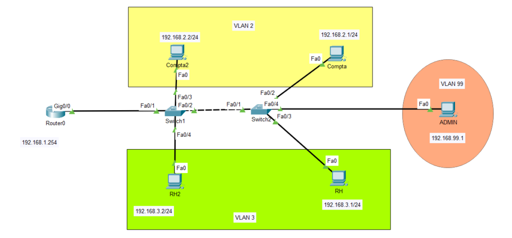
Nos VLANs sont configurés. On va maintenant ajouter un VLAN pour l’administration pour gérer les machines depuis le poste de l’administrateur. Enfin, nous relierons nos VLANs au routeur en créant des sub-interfaces.
Il faut d’abord créer le VLAN 99 pour l’administrateur sur l’interface Fa0/3 du switch2.
Switch>en
Switch#conf t
Enter configuration commands, one per line.  End with CNTL/Z.
Switch(config)#interface FastEthernet 0/4
Switch(config-if)#exit
Switch(config)#vlan 99
Switch(config-vlan)#name Admin
Switch(config-vlan)#exit
Switch(config)#interface FastEthernet 0/4

Switch(config-if)#switchport access vlan 99
Nous allons maintenant donner une adresse IP pour l’interface du VLAN 99.
Switch>en
Switch#conf t
Enter configuration commands, one per line.  End with CNTL/Z.
Switch(config)#vlan 2
Switch(config-vlan)#name compta
Switch(config-vlan)#state active
                    ^
% Invalid input detected at '^' marker.

Switch(config-vlan)#no shutdown
                       ^
% Invalid input detected at '^' marker.

Switch(config-vlan)#exit
Switch(config)#sh vlan brief
                ^
% Invalid input detected at '^' marker.

Switch(config)#show vl
Switch(config)#show vla
Switch(config)#show vlan bried
                ^
% Invalid input detected at '^' marker.

Switch(config)#show vlan brief
                ^
% Invalid input detected at '^' marker.

Switch(config)#exit
Switch#
%SYS-5-CONFIG_I: Configured from console by console

Switch#sh vlan brief

VLAN Name                             Status    Ports
---- -------------------------------- --------- -------------------------------
1    default                          active    Fa0/1, Fa0/2, Fa0/3, Fa0/4
                                                Fa0/5, Fa0/6, Fa0/7, Fa0/8
                                                Fa0/9, Fa0/10, Fa0/11, Fa0/12
                                                Fa0/13, Fa0/14, Fa0/15, Fa0/16
                                                Fa0/17, Fa0/18, Fa0/19, Fa0/20
                                                Fa0/21, Fa0/22, Fa0/23, Fa0/24
                                                Gig0/1, Gig0/2
2    compta                           active
1002 fddi-default                     active
1003 token-ring-default               active
1004 fddinet-default                  active
1005 trnet-default                    active
Switch#conf t
Enter configuration commands, one per line.  End with CNTL/Z.
Switch(config)#interface Fa
Switch(config)#interface FastEthernet 0/2
Switch(config-if)#switchport access vlan 2
Switch(config-if)#exit
Switch(config)#exit
Switch#
%SYS-5-CONFIG_I: Configured from console by console

Switch#show vlan id 2

VLAN Name                             Status    Ports
---- -------------------------------- --------- -------------------------------
2    compta                           active    Fa0/2

VLAN Type  SAID       MTU   Parent RingNo BridgeNo Stp  BrdgMode Trans1 Trans2
---- ----- ---------- ----- ------ ------ -------- ---- -------- ------ ------
2    enet  100002     1500  -      -      -        -    -        0      0

Switch#conf t
Enter configuration commands, one per line.  End with CNTL/Z.
Switch(config)#vlan 3
Switch(config-vlan)#name RH
Switch(config-vlan)#exit
Switch(config)#interface Fas
Switch(config)#interface FastEthernet 0/3
Switch(config-if)#switchport access vlan 3
Switch(config-if)#end
Switch#
%SYS-5-CONFIG_I: Configured from console by console

Switch#show vlan id 3

VLAN Name                             Status    Ports
---- -------------------------------- --------- -------------------------------
3    RH                               active    Fa0/3

VLAN Type  SAID       MTU   Parent RingNo BridgeNo Stp  BrdgMode Trans1 Trans2
---- ----- ---------- ----- ------ ------ -------- ---- -------- ------ ------
3    enet  100003     1500  -      -      -        -    -        0      0

Switch#


Switch con0 is now available


Press RETURN to get started.


%SPANTREE-2-RECV_PVID_ERR: Received 802.1Q BPDU on non trunk FastEthernet0/1 VLAN1.

%SPANTREE-2-BLOCK_PVID_LOCAL: Blocking FastEthernet0/1 on VLAN0001. Inconsistent port type.


%LINEPROTO-5-UPDOWN: Line protocol on Interface FastEthernet0/1, changed state to down

%LINEPROTO-5-UPDOWN: Line protocol on Interface FastEthernet0/1, changed state to up

%LINK-5-CHANGED: Interface FastEthernet0/4, changed state to up

%LINEPROTO-5-UPDOWN: Line protocol on Interface FastEthernet0/4, changed state to up


Switch>en
Switch#conf t
Enter configuration commands, one per line.  End with CNTL/Z.
Switch(config)#interface FastEthernet 0/4
Switch(config-if)#exit
Switch(config)#vlan 99
Switch(config-vlan)#name Admin
Switch(config-vlan)#exit
Switch(config)#interface FastEthernet 0/4

Switch(config-if)#switchport access vlan 99
Switch(config-if)#exit
Switch(config)#interface vlan 99
Switch(config-if)#
%LINK-5-CHANGED: Interface Vlan99, changed state to up

%LINEPROTO-5-UPDOWN: Line protocol on Interface Vlan99, changed state to up
Switch(config-if)#ip address 192.168.99.2 255.255.255.0
Switch(config-if)#no shutdown
Switch(config-if)#exit

Switch(config)#exit
Switch#
%SYS-5-CONFIG_I: Configured from console by console
show run
Building configuration...

Current configuration : 1245 bytes
!
version 12.2
no service timestamps log datetime msec
no service timestamps debug datetime msec
no service password-encryption
!
hostname Switch
!
!
!
!
!
!
spanning-tree mode pvst
spanning-tree extend system-id
!
interface FastEthernet0/1
!
interface FastEthernet0/2
 switchport access vlan 2
!
interface FastEthernet0/3
 switchport access vlan 3
!
interface FastEthernet0/4
 switchport access vlan 99
!
Vérifions maintenant que le poste de l’administrateur a bien accès au switch.
C:\>ping 192.168.99.2

Pinging 192.168.99.2 with 32 bytes of data:

Request timed out.
Reply from 192.168.99.2: bytes=32 time<1ms TTL=255
Reply from 192.168.99.2: bytes=32 time<1ms TTL=255
Reply from 192.168.99.2: bytes=32 time<1ms TTL=255

Ping statistics for 192.168.99.2:
    Packets: Sent = 4, Received = 3, Lost = 1 (25% loss),
Approximate round trip times in milli-seconds:
    Minimum = 0ms, Maximum = 0ms, Average = 0ms
Il nous faut maintenant ajouter ce VLAN 99 sur le switch 1 sans lui attribuer de port..
Switch>en
Switch#conf t
Enter configuration commands, one per line.  End with CNTL/Z.
Switch(config)#vlan 99
Switch(config-vlan)#name Admin
Switch(config-vlan)#exit
Puis on ajoute le VLAN 99 au trunk de chaque switch.
Le poste administrateur peut communiquer avec les 2 switchs.
Aussi, il faut bien configurer le trunk entre le routeur et le switch1 (autoriser les VLANs 2,3 et 99).
Nous allons maintenant relier nos VLANs au routeur. Nous allons devoir configurer un trunk sur le câble entre le routeur et le switch1. Mais, étant donné que le routeur n’a qu’une interface, nous allons créer des sub-interfaces pour chaque VLAN sur le routeur. Ces sub-interfaces seront reliées à l’interface physique du routeur.
routeur1(config)#interface GigabitEthernet 0/0/0
%Invalid interface type and number
routeur1(config)#interface GigabitEthernet 0/0
routeur1(config-if)#int G
routeur1(config-if)#int Gi
routeur1(config-if)#int GigabitEthernet 0/0.1
routeur1(config-subif)#
%LINK-5-CHANGED: Interface GigabitEthernet0/0.1, changed state to up

%LINEPROTO-5-UPDOWN: Line protocol on Interface GigabitEthernet0/0.1, changed state to up

routeur1(config-subif)#no shutdown
routeur1(config-subif)#encapsulation dot1Q 2
routeur1(config-subif)#ip address 192.168.2.254 255.255.255.0

routeur1(config-subif)#exit
routeur1(config)#exit
routeur1#
%SYS-5-CONFIG_I: Configured from console by console

routeur1#ping 192.168.2.1

Type escape sequence to abort.
Sending 5, 100-byte ICMP Echos to 192.168.2.1, timeout is 2 seconds:
.!!!!
Success rate is 80 percent (4/5), round-trip min/avg/max = 0/0/1 ms

routeur1#conf t
Enter configuration commands, one per line.  End with CNTL/Z.
routeur1(config)#interface GigabitEthernet 0/0
routeur1(config-if)#int GigabitEthernet 0/0.2
routeur1(config-subif)#
%LINK-5-CHANGED: Interface GigabitEthernet0/0.2, changed state to up

%LINEPROTO-5-UPDOWN: Line protocol on Interface GigabitEthernet0/0.2, changed state to up

routeur1(config-subif)#no shutdown
routeur1(config-subif)#encapsulation dot1Q 3
routeur1(config-subif)#ip address 192.168.3.254 255.255.255.0
routeur1(config-subif)#end
routeur1#
%SYS-5-CONFIG_I: Configured from console by console

routeur1#ping 192.168.3.1

Type escape sequence to abort.
Sending 5, 100-byte ICMP Echos to 192.168.3.1, timeout is 2 seconds:
.!!!!
Success rate is 80 percent (4/5), round-trip min/avg/max = 0/0/1 ms

routeur1#conf t
Enter configuration commands, one per line.  End with CNTL/Z.
routeur1(config)#interface gigabitEthernet 0/0
routeur1(config-if)#int GigabitEthernet 0/0.3
routeur1(config-subif)#
%LINK-5-CHANGED: Interface GigabitEthernet0/0.3, changed state to up

%LINEPROTO-5-UPDOWN: Line protocol on Interface GigabitEthernet0/0.3, changed state to up
no shutdown
routeur1(config-subif)#encapsulation dot1Q 99
routeur1(config-subif)#ip address 192.168.99.254 255.255.255.0
routeur1(config-subif)#end
Le routeur pinge bien les machines.
Il faut maintenant créer la route entre le VLAN 99 et les autres.
Visualisons d’abord les interfaces et les adresses IP sur le routeur.
routeur1#sh ip int brief
Interface              IP-Address      OK? Method Status                Protocol
GigabitEthernet0/0     192.168.1.254   YES manual up                    up
GigabitEthernet0/0.1   192.168.2.254   YES manual up                    up
GigabitEthernet0/0.2   192.168.3.254   YES manual up                    up
GigabitEthernet0/0.3   192.168.99.254  YES manual up                    up
GigabitEthernet0/1     unassigned      YES unset  administratively down down
GigabitEthernet0/2     unassigned      YES unset  administratively down down
Vlan1                  unassigned      YES unset  administratively down down
Puis sur les machines, on ajoute les passerelles.
| Admin | 192.168.99.254 |
| Compta | 192.168.2.254 |
| RH | 192.168.3.254 |
Nous avons vu brièvement la segmentation logique de réseaux. Cet article n’est pas exhaustif concernant la sécurité (sécurisation des switchs, accès à distance).
A noter: Les VLANs doivent être créés avant de faire les trunks !
Voici la configuration des éléments:
Le routeur
Router#show run
Building configuration...

Current configuration : 1040 bytes
!
version 16.6.4
no service timestamps log datetime msec
no service timestamps debug datetime msec
no service password-encryption
!
hostname Router
!
!
!
!
!
!
!
!
ip cef
no ipv6 cef
!
!
!
!
!
!
!
!
!
!
!
!
spanning-tree mode pvst
!
!
!
!
!
!
interface GigabitEthernet0/0/0
 no ip address
 duplex auto
 speed auto
!
interface GigabitEthernet0/0/0.1
 encapsulation dot1Q 1 native
 ip address 192.168.1.254 255.255.255.0
!
interface GigabitEthernet0/0/0.2
 encapsulation dot1Q 2
 ip address 192.168.2.254 255.255.255.0
!
interface GigabitEthernet0/0/0.3
 encapsulation dot1Q 3
 ip address 192.168.3.254 255.255.255.0
!
interface GigabitEthernet0/0/0.99
 encapsulation dot1Q 99
 ip address 192.168.99.254 255.255.255.0
!
interface GigabitEthernet0/0/1
 no ip address
 duplex auto
 speed auto
 shutdown
!
interface GigabitEthernet0/0/2
 no ip address
 duplex auto
 speed auto
 shutdown
!
interface Vlan1
 no ip address
 shutdown
!
ip classless
!
ip flow-export version 9
!
!
!
!
!
!
!
!
line con 0
!
line aux 0
!
line vty 0 4
 login
!
!
!
end
Le switch 1
Switch#show run
Building configuration...

Current configuration : 1388 bytes
!
version 12.2
no service timestamps log datetime msec
no service timestamps debug datetime msec
no service password-encryption
!
hostname Switch
!
!
!
!
!
!
spanning-tree mode pvst
spanning-tree extend system-id
!
interface FastEthernet0/1
 switchport trunk allowed vlan 2-3,99
 switchport mode trunk
!
interface FastEthernet0/2
 switchport trunk allowed vlan 2-3,99
 switchport mode trunk
!
interface FastEthernet0/3
 switchport access vlan 3
 switchport mode access
!
interface FastEthernet0/4
 switchport access vlan 2
 switchport mode access
!
interface FastEthernet0/5
!
interface FastEthernet0/6
!
interface FastEthernet0/7
!
interface FastEthernet0/8
!
interface FastEthernet0/9
!
interface FastEthernet0/10
!
interface FastEthernet0/11
!
interface FastEthernet0/12
!
interface FastEthernet0/13
!
interface FastEthernet0/14
!
interface FastEthernet0/15
!
interface FastEthernet0/16
!
interface FastEthernet0/17
!
interface FastEthernet0/18
!
interface FastEthernet0/19
!
interface FastEthernet0/20
!
interface FastEthernet0/21
!
interface FastEthernet0/22
!
interface FastEthernet0/23
!
interface FastEthernet0/24
!
interface GigabitEthernet0/1
!
interface GigabitEthernet0/2
!
interface Vlan1
 no ip address
 shutdown
!
interface Vlan99
 mac-address 0001.c9e1.7001
 ip address 192.168.99.1 255.255.255.0
!
!
!
!
line con 0
!
line vty 0 4
 login
line vty 5 15
 login
!
!
!
!
end
Le switch 2
Switch#show run
Building configuration...

Current configuration : 1354 bytes
!
version 12.2
no service timestamps log datetime msec
no service timestamps debug datetime msec
no service password-encryption
!
hostname Switch
!
!
!
!
!
!
spanning-tree mode pvst
spanning-tree extend system-id
!
interface FastEthernet0/1
 switchport trunk allowed vlan 2-3,99
 switchport mode trunk
!
interface FastEthernet0/2
 switchport access vlan 99
!
interface FastEthernet0/3
 switchport access vlan 3
 switchport mode access
!
interface FastEthernet0/4
 switchport access vlan 2
 switchport mode access
!
interface FastEthernet0/5
!
interface FastEthernet0/6
!
interface FastEthernet0/7
!
interface FastEthernet0/8
!
interface FastEthernet0/9
!
interface FastEthernet0/10
!
interface FastEthernet0/11
!
interface FastEthernet0/12
!
interface FastEthernet0/13
!
interface FastEthernet0/14
!
interface FastEthernet0/15
!
interface FastEthernet0/16
!
interface FastEthernet0/17
!
interface FastEthernet0/18
!
interface FastEthernet0/19
!
interface FastEthernet0/20
!
interface FastEthernet0/21
!
interface FastEthernet0/22
!
interface FastEthernet0/23
!
interface FastEthernet0/24
!
interface GigabitEthernet0/1
!
interface GigabitEthernet0/2
!
interface Vlan1
 no ip address
 shutdown
!
interface Vlan99
 mac-address 00d0.bc17.c401
 ip address 192.168.99.2 255.255.255.0
!
!
!
!
line con 0
!
line vty 0 4
 login
line vty 5 15
 login
!
!
!
!
end

